Pro-Form 520 User Manual
Browse online or download User Manual for Treadmills Pro-Form 520. Pro-Form 520 User`s manual
- Page / 32
- Table of contents
- TROUBLESHOOTING
- BOOKMARKS
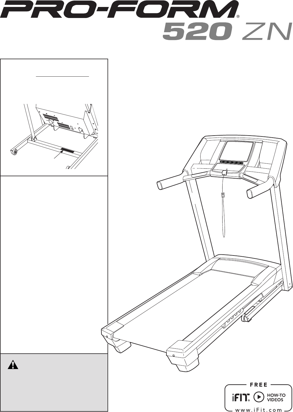
- USER’S MANUAL 1
- WARNING DECAL PLACEMENT 2
- TABLE OF CONTENTS 2
- IMPORTANT PRECAUTIONS 3
- SAVE THESE INSTRUCTIONS 4
- BEFORE YOU BEGIN 5
- PART IDENTIFICATION CHART 6
- ASSEMBLY 7
- OPERATION AND ADJUSTMENT 13
- ETPF59112 14
- (PFTL59112) 14
- TROUBLESHOOTING 23
- EXERCISE GUIDELINES 26
- PART LIST 27
- EXPLODED DRAWING A 28
- EXPLODED DRAWING B 29
- EXPLODED DRAWING C 30
- EXPLODED DRAWING D 31
- ORDERING REPLACEMENT PARTS 32
- LIMITED WARRANTY 32
Summary of Contents
USER’S MANUAL CAUTIONRead all precautions and instruc-tions in this manual before using this equipment. Keep this manual for future reference.Model
107. Insert the Upright Wire (70) into the Left Upright (75) as you set the console assembly on the Left Handrail (71) and the Right Handrail (72).
118. Attach the console assembly to the Left Handrail Tube (34) and the Right Handrail Tube (35) with four #8 x 3/4" Screws (6); start all four
1211. Make sure that all parts are properly tightened before you use the treadmill. If there are sheets of plastic onthetreadmilldecals,remove
13OPERATION AND ADJUSTMENTHOW TO CONNECT THE POWER CORDUse a Surge SuppressorYour treadmill, like other electronic equipment, can be damaged by sudden
14CONSOLE DIAGRAM ETPF59112(PFTL59112)FEATURES OF THE CONSOLE The treadmill console offers an impressive array of features designed to make your worko
15HOW TO TURN ON THE POWERIMPORTANT: If the treadmill has been exposed to cold temperatures, allow it to warm to room tem-perature before turning on t
16 • Thenumberofverticalfeetyouhaveclimbed •Thespeedofthewalkingbelt •Yourheartrate(seestep6) • Thematrix The matri
17HOW TO USE A WEIGHT-LOSS WORKOUT1. Insert the key into the console. See HOW TO TURN ON THE POWER on page 15. 2. Select a time for the workout
18HOW TO USE A SET-A-GOAL WORKOUT1. Insert the key into the console. See HOW TO TURN ON THE POWER on page 15.2. Select a set-a-goal workout. To
19HOW TO USE AN IFIT WORKOUTNote: To use an iFit workout, you must have an optional iFit module. To purchase an iFit module at any time, go to www.iFi
2WARNING DECAL PLACEMENTThis drawing shows the locations of the warn-ing decals. If a decal is missing or illegible, call the telephone number on the
20 6. Follow your progress with the displays. See step 5 on page 15. The My Trail tab will show a map of the trail you are walking or running o
21THE INFORMATION MODEThe console features an information mode that keeps track of treadmill information and allows you to person-alize console settin
22 HOW TO FOLD THE TREADMILLTo avoid damaging the treadmill, adjust the incline to the lowest position before you fold the treadmill. Then, remove the
23Most treadmill problems can be solved by follow-ing the simple steps below. Find the symptom that applies, and follow the steps listed. If further a
24 Lower the treadmill (see HOW TO LOWER THE TREADMILL FOR USE on page 22). Remove the three #8 x 3/4" Screws (6). Carefully slide the Motor Ho
25SYMPTOM: The walking belt is off-center or slips when walked ona. If the walking belt is off-center,rstremovethekey and UNPLUG THE POWER CORD
26EXERCISE GUIDELINESThese guidelines will help you to plan your exercise program. For detailed exercise information, obtain a reputable book or consu
27 Key No. Qty. Description Key No. Qty. Description 1 5 #8 x 1/2" Ground Screw 2 2 3/8" x 2 1/2" Bolt 3 5 3/8" Nu
2851272524244141423839504914373227234729422829281919191453352254043441246484819451919191919131161656951936243624291919291924241919EXPLODED DRAWING AMo
29941666765616362158595818202160226576643317172021618186666668663066EXPLODED DRAWING BModel No. PFTL59112.0 R0812A
31. It is the responsibility of the owner to ensure that all users of this treadmill are adequately informed of all warnings and precautions.2. Befo
308078157715782813963281967967196967979797777858545544534974769337889757073378786974357771737677273886666EXPLODED DRAWING CModel No. PFTL59112.0 R0812
3191683949431848687906826668915469797979769255979766976694942669466669797661110684889493EXPLODED DRAWING DModel No. PFTL59112.0 R0812A
Part No. 335767 R0812A Printed in USA © 2012 ICON IP, Inc.ICON Health & Fitness, Inc. (ICON) warrants this product to be free from defects in wor
420. The heart rate monitor is not a medical device. Various factors, including the user’s movement, may affect the accuracy of heart rate readings. T
5Thank you for selecting the new PROFORM® 520 ZN treadmill. The 520 ZN treadmill provides an impressive selection of features designed to make your wo
6PART IDENTIFICATION CHARTUse the drawings below to identify small parts used for assembly. The number in parentheses below each draw-ing is the key n
7ASSEMBLY• To hire a service technician to assemble this prod-uct in your home, call 1-800-445-2480. • Assembly requires two persons.• Place all pa
82. Identify the Left Upright (75). Have a second person hold the Left Upright near the Base (80). See the inset drawing. Tie the wire tie in the
94. Identify the Left Handrail (71). Remove the tie from the 5/16" Cage Nut (33). If necessary, press the Cage Nut back into place. Hold the
More documents for Treadmills Pro-Form 520


Related products and manuals for Treadmills Pro-Form 520
 (18 pages)
(22 pages)
(32 pages)
(36 pages)
(18 pages)
(18 pages)
(28 pages)
(27 pages)
(36 pages)
(26 pages)
(32 pages)
(36 pages)
(18 pages)
(22 pages)
(32 pages)
(36 pages)
(18 pages)
(18 pages)
(28 pages)
(27 pages)
(36 pages)
(26 pages)
(32 pages)
(36 pages)
© 2020, manymanuals.com. All rights reserved. | 0.066 s |
 Manymanuals.com
 Manymanuals.de
 Manymanuals.fr
 Manymanuals.it
 Manymanuals.pl
 Manymanuals.cz
 Manymanuals.es
 Manymanuals-pt.com
Comments to this Manuals